
Guided Workflow | Modeling an As-Built Steel Structure
In this exercise, you will learn how to prepare and leverage the scan of an industrial site to accurately extract a steel framework.
Exercise overview:
Open the file OilSite.3dr (download).
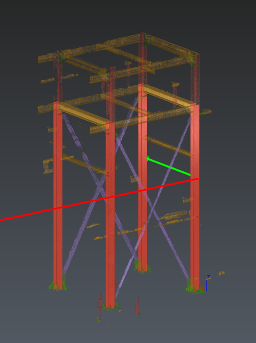
This dataset is a selected area of an oil site. You can navigate through the data and understand the environment.
For convenience, the point cloud has already been classified using the Plant model.
Create a UCS aligned with the steel structure
Creating a UCS aligned to your steel structure will help you to save time during extraction.
You can use the Corner tool to easily create a coordinate system from two perpendicular planes.
Locate the cement block next to the position
27,43; -23,01; -1,55.Run Corner tools and hover on the external corner. The coordinate system will be previewed.
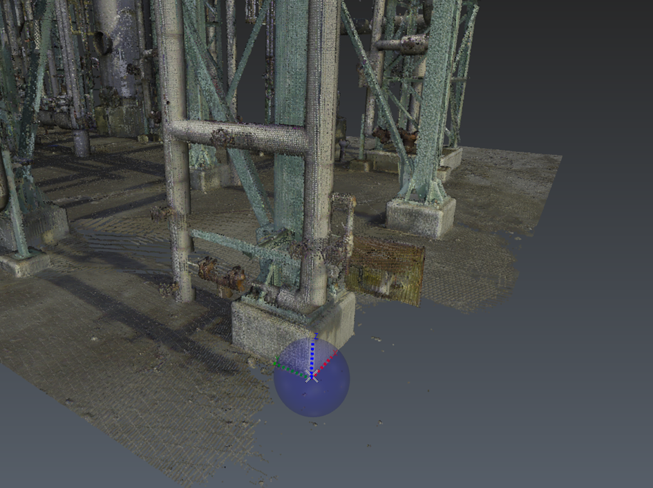
Previewed coordinate system while hovering the cement block.
Click and press ENTER to validate the new coordinate system.
Change the origin of the UCS to match the baseplate of the closest steel column.
Run Change Origin.
Enable the XYZ mode in the toolbar.
Copy the following coordinates
0,05073; 0,04783; 0,28794Validate.
(optional) Rename the UCS.
Select the point cloud and launch Scan to Steel.
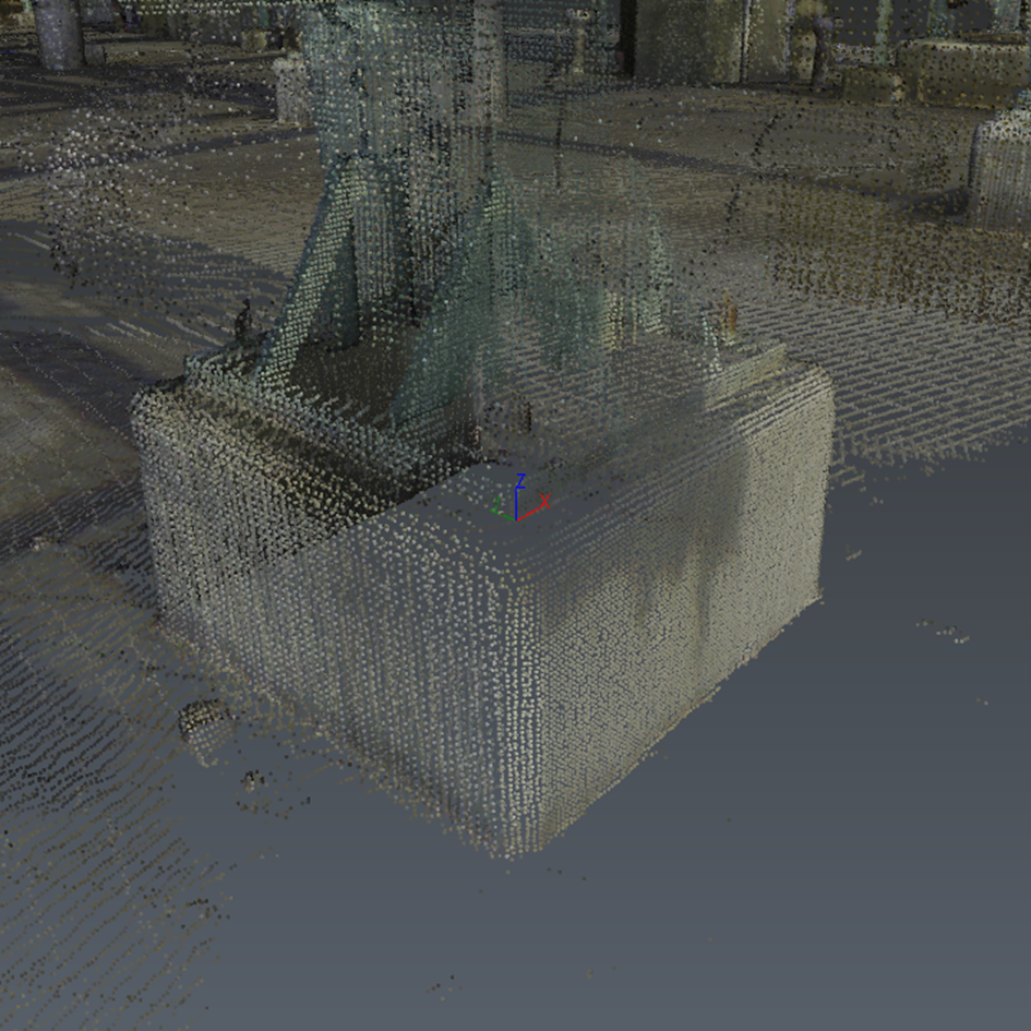
Final UCS.
Defining levels to handle multi-storey steel extraction
The first step of the workflow is to define the different levels to be extracted from the point cloud.
If the steel structure spans multiple levels, taking the time to set them up now will make the rest of the workflow much easier, especially:
to easily extend column at the same elevation,
to clone steel elements from one level to another,
to organize the elements in the output files (e.g., IFC).
By default, the first level is created at Z=0, using the active coordinate system.
If the classification is available, the command automatically switches the point cloud display to it.
Click on the ‘+’ button in the command. A new level is created.
Double click its elevation in the Elevation column to set the elevation to “5.55”.
Press ENTER to validate.
In the same way, add another level at Z=7.05.
Double-click on levels name in the list to rename them “Base”, “Level 1”, “Level 2”.
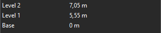
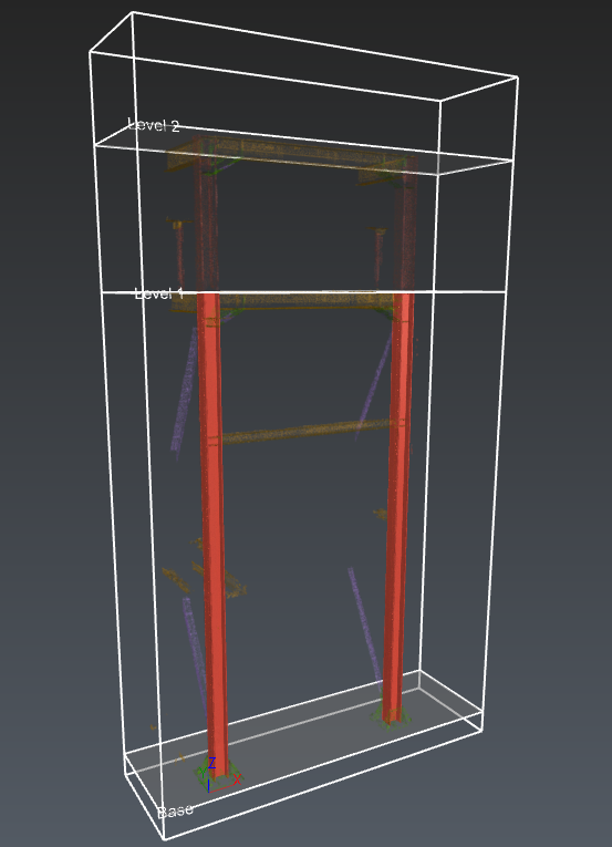
Created levels
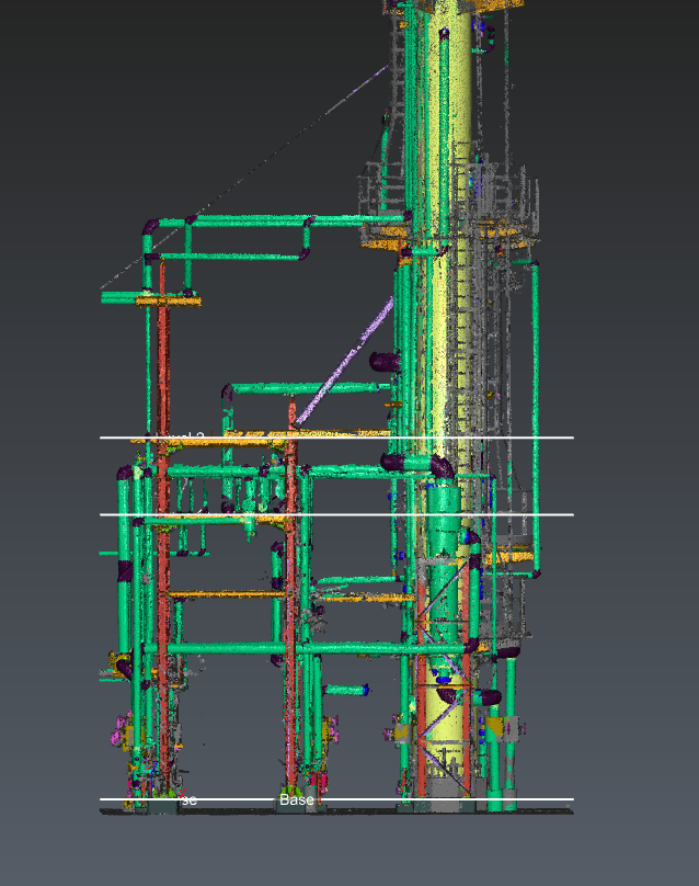
Preview of the levels in the 3D scene.
Extracting columns and beams from the point cloud
The levels are now set up correctly.
Exit the Scan to Steel workflow.
Activate the clipping box “Extraction”.
Run the workflow again.
Click Next to move on to the Steel Extraction step. It allows extracting the elements of the steel structure from three categories: Beam, Column and Other elements (such as struts).
Adjust the scene display to help you focus on the elements you want to extract:
Expand the cloud filter menu and keep only Steel-related classes visible. Hold CTRL while clicking class checkboxes to show only the selected classes.
Set the point cloud opacity to about 30%.
Hide the levels.
Tips
Adjust the point size with ALT+mouse wheel during extraction to inspect local areas without changing the command’s visibility settings.
Activate the Column mode in the toolbar.
Select the Europe standard.
Set the type to be extracted to I-Beam.
Enable the Force vertical and Snap to levels options.
Locate the column next to the coordinate system
Click a point in the center area
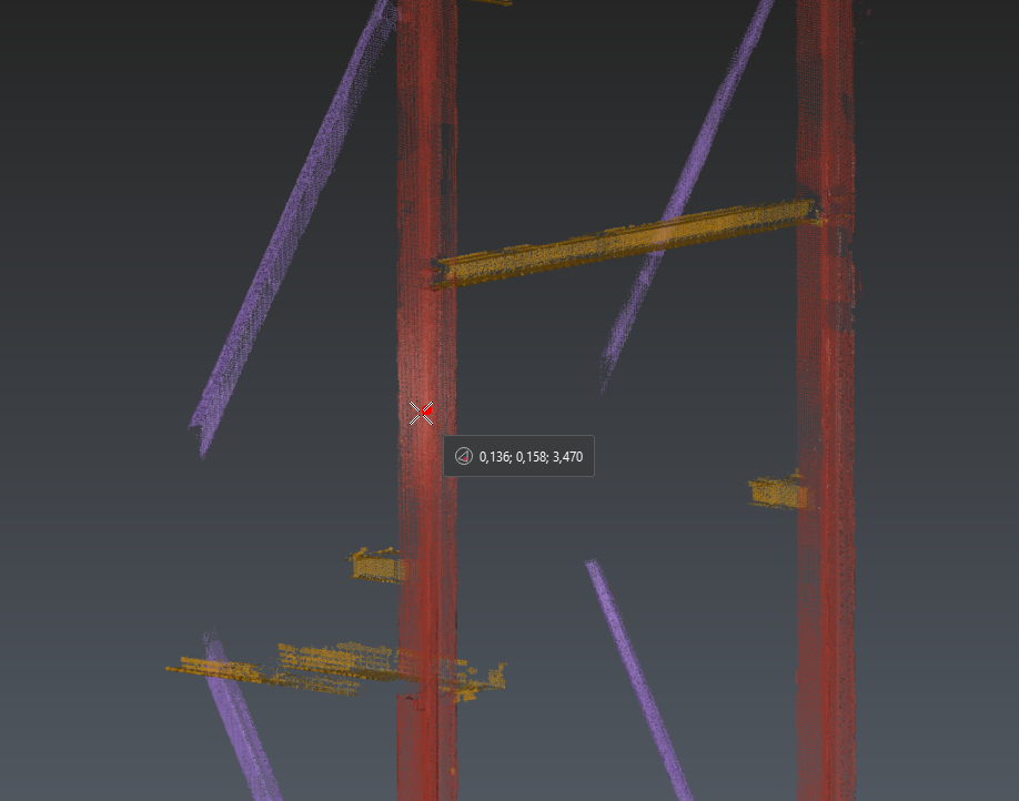
Click in the center of the column to extract from a single point.
Press ENTER to run the extraction.
Tips
If the area is too challenging (noise), you can click a second point on another face of the scanned element to improve the automatic reference selection. The extraction starts automatically after the second click.
Consider the scanner position to select the most reliable faces for the extraction.
Try to avoid areas with noise or including non-relevant points (for example, next to corners where other elements intersect).
The column is extracted. You can now review the selected reference and check the related metrics: the Overall error and the Coverage for each reference.
Check that the selected Reference is “HE180A”. Otherwise, select it from the list.
Repeat the same steps to extract the second column.
The two extracted columns.
Now, activate the Beam mode in the toolbar to extract the beam element located at the top of both columns:
Check that Force horizontal is enabled.
Using the same principles as before, click two points that are far enough apart on two distinct faces of the beam.
For example, click the first point on the underside around X=0.9, and the second one on the lateral side around X=2.0.Check that the extracted Reference is “HE180A”.
The extracted beam.
Once the three elements have been extracted, adjust the alignment using their respective axes.
Select the first column and ensure its axis position is set to Bottom Center so that it is located to the inside of the arch. Depending on the extraction, it might be Top Center.
New axis position of the first column.
Do the same with the second column.
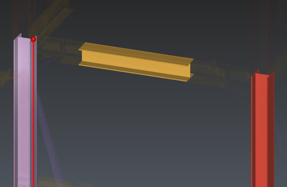
Select the beam and set the axis position to the highest position along the elevation. Depending on the extraction, it can be Bottom Center or Top Center.

New axis position of the beam.
Activate the Alignment mode in the toolbar to make sure that all elements are perfectly aligned with one another.
Select the three elements by following the order: column 1, column 2, beam.
Check the previewed result and validate it with ENTER.
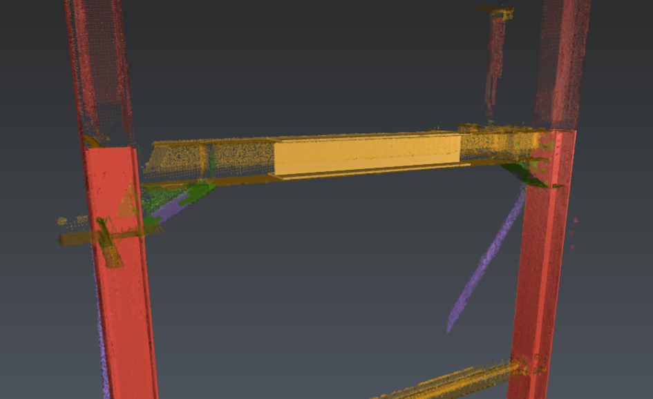
The beam is now extended and aligned with the column axes.
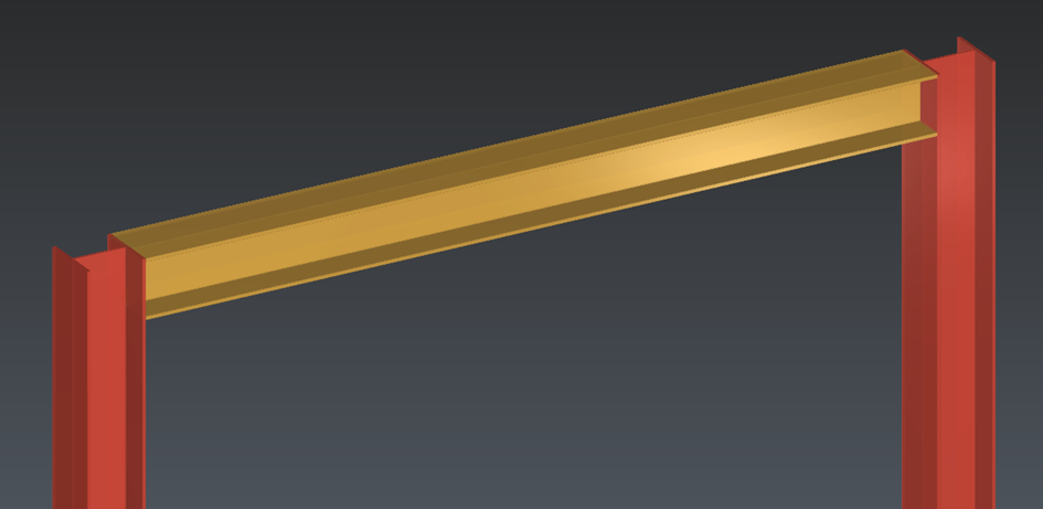
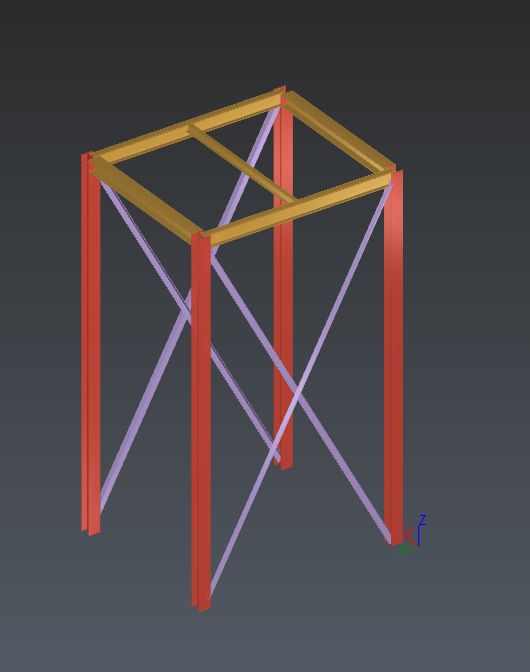
The three extracted elements.
Duplicating elements
Since the structure is made of repetitive elements, you can duplicate the first three first elements instead of extracting them again.
Exit the workflow.
Display both polylines “Steel Direction 1” and “Steel Direction 2”.
Make sure the limit box is still enabled.
Run again the workflow.
Hide the levels again and show only the relevant classes.
Edit the limit box (CTRL+Space) to extend the clipping area until the second set of columns is visible. For example, set the Y length around 4.5 m.
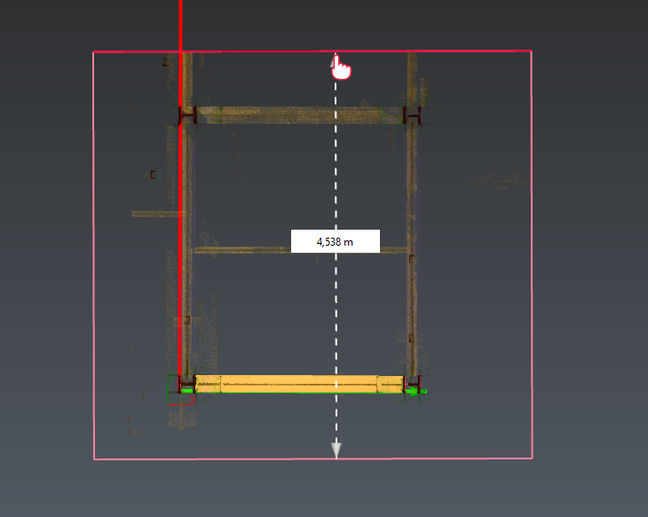
New size of the limit box from the Top View.
You can now copy the elements:
Activate the Duplicate mode in the toolbar. This mode lets you copy the selected elements one or multiple times. Copied elements are previewed in real time.
Select both columns and the beam by holding CTRL (in the graphic scene or in the Extraction result console).
In the left panel, select the Repeat mode.
Activate the Direction tool and select the Direction option.
Click on the red polyline to set up the Direction option from it, then press ENTER.
Set the Step to 3 m and Repetitions to 1.
The temporary copy should now be at the right position. Check the positioning by changing the point cloud display (visibility and/or transparency).
Press ENTER to validate the copy.
Three new elements have been duplicated
Extract struts and remaining beams
Extract struts
Exit the workflow and hide the polylines.
Run the workflow again.
In the class filter, enable only the Steel structure diagonal class. If necessary, adjust the limit box size again to make the elements visible (CTRL+Space).
Select the Others mode to extract the first pair of struts.
Set Standard to Europe.
Set Type to Corner.
Set Constraint to None.
Click a single point on a fully scanned area and then press ENTER or click two points to run the extraction.
Check that the selected Reference is “L80X10”. If not, select it from the list.
Switch to Select mode.
Slide both ends of the strut to extend them to the desired position. Setting the camera to -X may help during the edition.
Extract the second strut the same way, then repeat the process for the second pair of struts.
Check that the same reference is extracted for all struts.
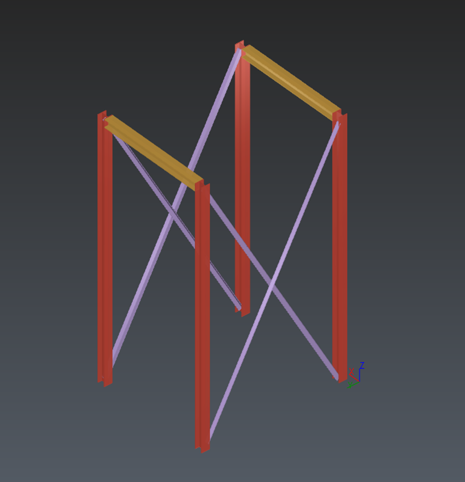
The four extracted struts.
Extract other beams
You can now extract and connect the other beam elements at the top of the first level:
One beam of type Europe / IPE120 in the center.
Two beams of type Europe / IPE200 on the other side.
Additional beams on the first level.
Scaling the model up to the next level
The first level is now done.
Hide the point cloud and show the Levels.
Select the four beams in the graphic scene or in the left panel.
Launch Duplicate mode.
Configure the copy settings:
Set the direction to Z.
Set Step to 1.5 m.
Set Repetitions to 1.
Press ENTER to validate.
The new elements are still assigned to the first level though:
Go back to Select mode and select the newly duplicated beams.
In the left panel, change their Level from “Base” to “Level 1”. You can see effective change in the steel hierarchy tree.
Tips
The ‘Properties’ panel on the left can be collapsed to view and/or select information more easily.
Extend the columns:
Select one of the columns.
Click the upper handle of its axis. The clicking-point tools open so you can define a new end point.
Set the alignment mode to Vertex End, then place the cursor on a corner of the target level (for example, Level 2), then click to validate the new point. The column is now extended to the next level.
Repeat these steps for the three other columns.
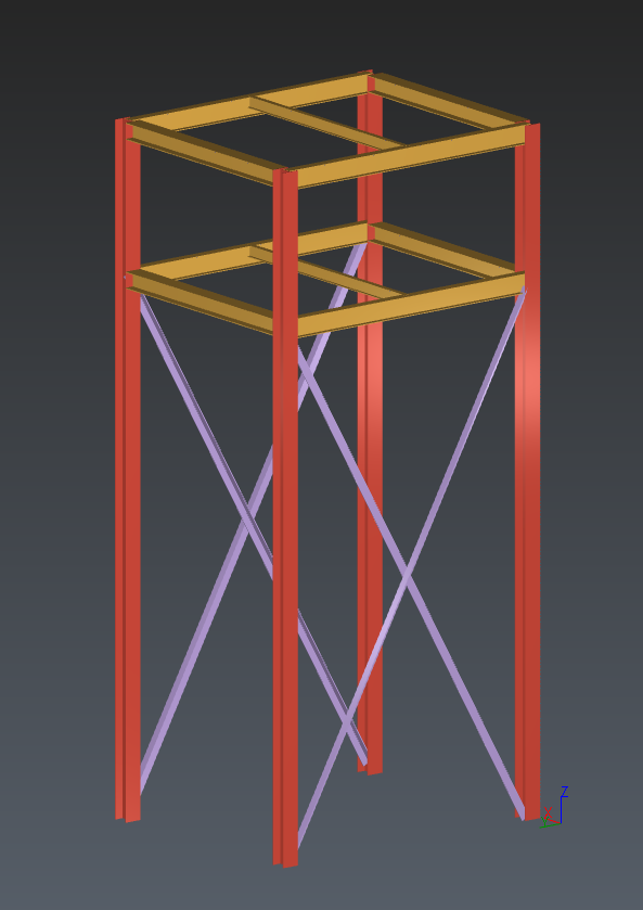
Final steel structure.
Export the steel model to IFC (BIM)
The model is now complete.
Click Next to open the Export step and generate an output file.
Select BIM as the export option.
(optional) You can filter the exported elements:
Enable Selected elements to limit the export to specific objects.
In the Level section, locate the “Base” level
Uncheck the Others category to filter out the extracted struts.
Click Export, choose a destination folder, and save the result as an IFC file.
Exit the workflow.