
Image management
Project
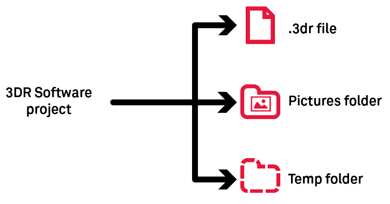
Pictures folder must follow the .3dr when you share your project.
Temp folder stores temporary images which are necessary while the project is open.
Image types
Type | Comment |
|---|---|
Unknown/Abstract | This is the default type when the type is unknown. Use Edit Images to set the image type. |
Perspective | Type for pinhole images (usual photography from a camera). |
Ortho-image | Similar to a raster map (contrary to perspective). You can create such images using Extract OrthoImage. |
Cubeface | They are a set of 6 images on a cube (images share the same position). This object is not created by Cyclone 3DR, but are either imported as 6 independent images or as a spherical image. |
Spherical image | Also called pano(ramic). This image is equivalent to a cubeface. |
Images from LGSx
With the capacity to stream images from LGSx files, it is not required to convert the project to visualize the camera images anymore. However, it remains necessary to convert them when the images are used for advanced processing:
Feature | Comment |
It is mandatory to convert the images from the LGSx when a texturing workflow with images is expected by the user. | |
In the object explorer, only the converted images from the LGSx file can be grouped and ungrouped. |
Set of images
Perspective and spherical images can be stored either individually or grouped in a set of images.
In a set of images, images are also grouped by position. These positions are displayed in the scene like any scan position (Image Navigation Toolbar) and these positions are the access point to display images through the 3D scene.
Image display
Position display in the 3D scene | Full display in the 3D scene | Display in a 2D layout | |
|---|---|---|---|
Spherical (individual or within an image set) | Activate the display of positions (Image Navigation Toolbar). This display can be toggled object per object using the treeview. |
|
|
Perspective (individual or within an image set) | |||
Ortho-image |
| Use Go to camera viewpoint from the treeview. | Use Image Preview from the ribbon or the treeview. |
Unknown |
|
|
Display from the camera viewpoint (image navigation or "go to camera viewpoint")
This display will use external and internal parameters. Consequently, you can use the image to draw objects.
How to import data?
Images stored on your local or remote drive: Import
Images stored in CloudWorx clouds (jsa, lgs): Convert Project (after opening the corresponding files)
Images stored in e57: Import
Images stored in a textured mesh: Extract Textures
Images stored in FIELD 360 jobs: Cyclone FIELD 360
The maximum number of pixels to import is 2^30, which is about 1 073 million.
Refer to SImage, SSurveyingFormat and SCwCloud classes to import images through a script.
How to complete data (External and Internal parameters)?
Perspective | Ortho-Image | Spherical | |
|---|---|---|---|
Internal and/or External | External | External | |
Internal and/or External | External | External | |
Internal | N/A | N/A | |
Internal and/or External | External | External |
How to share georeferencing?
Ortho-Image: World files
This definition follows the ESRI standard (refer to word files).
Perspective: Excam and Incam files
These files are related to perspective images
Excam: External parameters (.excam)
This file stores parameters which define the point of view:
position
orientation
3DReshaper camera external parameters
X = 1.74146e+06
Y = 2.29867e+06
Z = 696.503
#Orientation is given with Euler angles in radians
Omega = -0.659887
Phi = 0.884306
Kappa = 2.46287
Incam: Internal parameters (.incam)
This file stores internal camera data collected from a camera calibration:
sensor size
focal length
PPA
PPS
distorsions
3DReshaper camera internal parameters
WIDTH=0.04896000027656555
HEIGHT=0.03672000020742416
PIXELSIZE=9.000000318337698e-06
PIXELRATIO=1
PPA=-2.499999936844688e-05; -0.0002979999990202487
PPS=-1.082631133721602e-06; 3.390730833438562e-05
FOCAL=0.03512400016188622
K0=0
K1=0.062675787745
K2=-0.30013658211
K3=0.29014370032
K4=0
K5=0
K6=0
P1=0.00014974133558
P2=-7.914469536399999e-06
Images rotation and standards
Perspective images
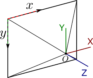
The original pose of a camera (without any translation or rotation) is given in the PATB convention. In this configuration the image point of view (optical center) is located on the scene origin, the view direction is oriented toward -Z axis, the top direction of the image is given by the Y axis and the right direction of the image given by the X axis.
This basic orientation is different from the image inner pixel axis regarding the Y axis. Other basic orientations exist and each image acquisition device or software giving external parameter is susceptible to use a different basic orientation. When applying to the image a rotation given within a particular basic orientation, a first rotation must be applied to switch from the PATB convention basic orientation to the considered basic orientation.
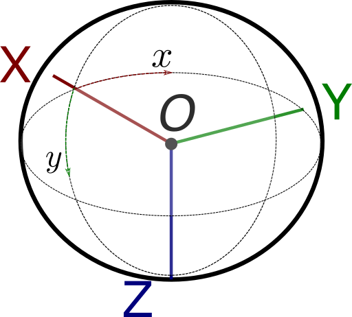
Spherical images
The original pose of a spherical image (without any translation or rotation) is the following. The spherical image center is located on the scene origin, the center of the spherical image corresponds to the X axis, the top direction of the image is given by the -Z axis and the right direction of the image given by the Y axis.
Photogrammetry angles (ω φ κ)
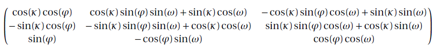
The main image orientation process consists in providing for each image to texture three photogrammetric angles that will define the image orientation in the scene. The supported rotation convention is the Standard Omega Phi Kappa (Euler Angles)
In this rotation configuration, the rotation is performed in the Order X => Y => Z.
The rotations values are given by omega, phi and kappa Ox(ω), Oy(φ), Oz(κ).
The rotation matrix corresponding to this rotation is computed as follows:
Perspective projection model
Classical perspective projection using a standard pinhole camera model coupled with lens radial and tangential distortions are expressed as follows:
Knowing a 3D Point P located at the coordinates [X Y Z] in the world coordinate system, the first step is to compute the point P coordinates in the camera coordinate system. This point P in the camera coordinates system can be expressed as P' of coordinates [X' Y' Z'] such as P' = R P + t. With R the rotation matrix and t the camera position in the world coordinates as expressed in the camera external parameters.
The homogeneous coordinates of the point P' are computed to obtain the point p = [X' / Z' Y' / Z' Z' / Z'] = [x y 1]
This point p is then shifted according to the principal point of symmetry (PPS [xp yp]) location such as x' = x - xp and y' = y-yp
Using these centered coordinates the computation of the distortions is possible.
Radial distortions | Tangential distortions |
|---|---|
We don't have a way to export this macro. | We don't have a way to export this macro. |
The distorted point coordinates are simply:
From these distorted coordinates, the final UV coordinates are obtained as:
How to texture?
You can texture and edit thanks to commands below:
Texturing masks
A mask is a black and white copy of the image saved in the same folder that can be displayed using Image Preview. Black areas correspond to ignored areas when texturing with the Smart Texture command; white areas will be used when texturing.
These masks are generated automatically while importing images or using Edit Mask.
Note that:
images imported in 2022.0 and previous versions haven't got masks.
the mask can be corrupted (wrong file path, mask image with another dimensions...).
How to export data?
Commands | Formats |
|---|---|
| |
Edit Images thanks to Save button | excam + incam |
JPG, BMP, PNG, TIF + world files | |
Send To (through Extract OrthoImage) | ortho-image |
Script (refer to SImage documentation) | JPG, BMP, PNG, TIF + world files |