
Guided Workflow | Extract Pipe Traces Using Catalog References
In this exercise, you will create a model of pipe traces.
Open the file PipeTraces.3dr (download).
Extraction
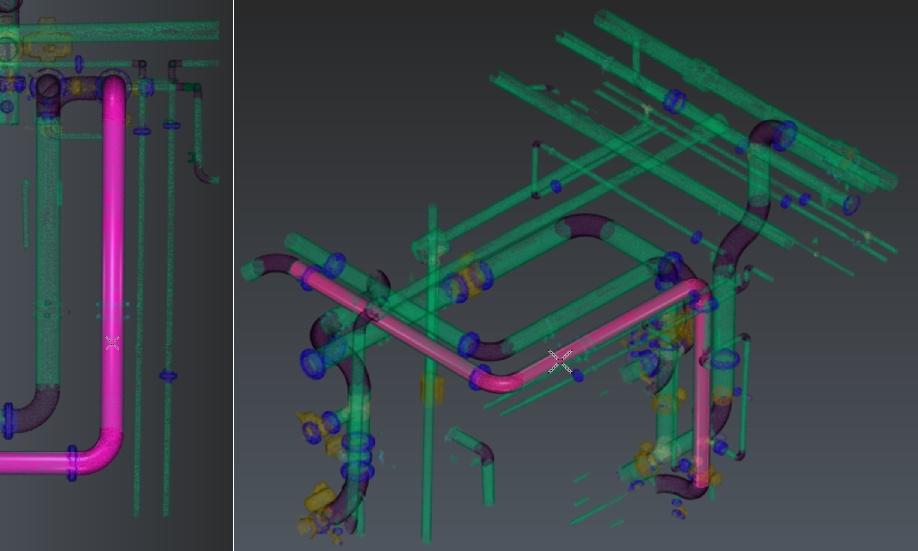
Select the cloud and launch Scan To Pipe. Set extraction mode to catalog: select ISO catalog. Using the classification filter, uncheck unclassified and steel structure points to hide the ground and steel elements, thus helping the extraction algorithm.
Tips
You may also hide classes representing objects that can not be extracted by Scan to Pipe tool, such as Tanks or Valve handles.
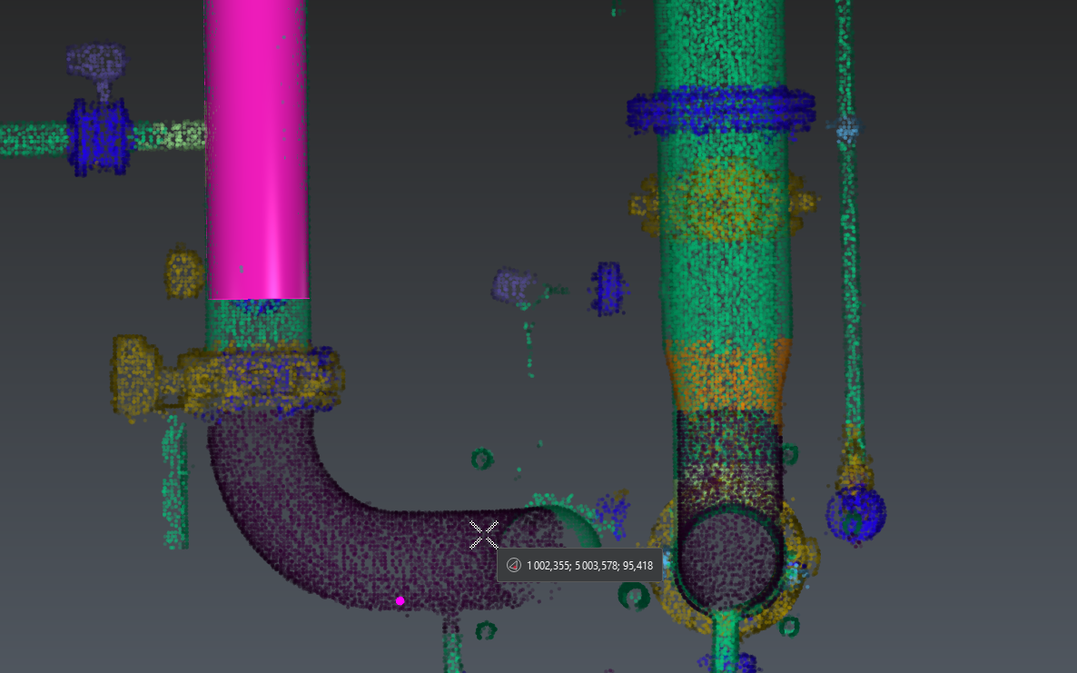
Select Start new trace. Use the Auto extraction tool and check Symmetric reducer: for best best results, click on a well-defined, low noise and long enough straight pipe. It is not necessary to begin with an extremity because any extremity of the trace can be extended at any time.
One click auto-extraction
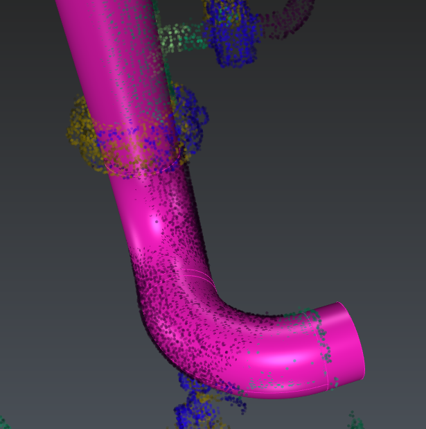
In Adaptive and Real extraction modes, check Use standard angles to constrain the elbows to common values: here we got two exact 90° angle elbows. Extraction may differ slightly according to the clicked point.
The auto extraction tool did not extract the whole trace. With the tool still active, click on a further part of the cloud. The trace will be extended.
Continue auto-extraction
At any point, if the extraction is not satisfying, press Delete on the keyboard to cancel the latest extraction and continue from where you were previously.
If you want to extract elements that are less well-defined and / or incomplete, you can switch to semi-automatic extraction. Select Elbow + Straight pipe mode and click two points on the opposite extremities of the next straight to extract to get a finer result:
Semi-automatic extraction
Note that the end to be extended or reduced will be found automatically. The workflow works the same for extracting reducers as well as for straight pipes.
Flanges work differently: they rely on an existing straight element. Select a trace and click Continue trace. Click Flange in the toolbar and extract a flange on the upper part of the extracted trace.
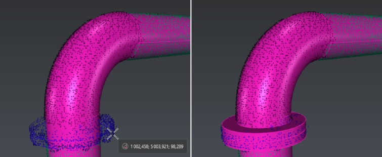
Extract flange from cloud
As well, if the extraction did not go well, press DELETE to make a new extraction.
Click Validate trace and exit to quit the extraction tool. Repeat this workflow to extract all the desired pipe traces:
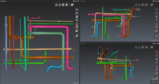
Completed extraction
When all traces are drawn, go to the next workflow step: Export pipes.
Export
For BIM export, you can rename pipe elements and give them a thickness using the list (double click on the default thickness). Otherwise, select directly the appropriate export among:
COE: pipe traces, optionally export the nominal diameter instead of the external diameter.
BIM: pipe traces, optionally as parametric solids.
Mesh: pipe traces, optionally with textures, will be exported with discretized surfaces. Optionally, send directly the traces to another application: refer to Send to.
CAD: pipe traces will be exported using geometrical CAD shapes.
Linear: only the center axis and the profiles will be exported.
Table of pipes information: a csv table describing the traces will be exported.